 Powerlink module object for ABB Frequency converter ACS880. This
 object contains an ABB_ACS880_Epl_IoModule object, reflecting the
 the Powerlink message. The IoModule object should be connected on
 object of class ABB_ACS880_Epl_1 in the plant hierarchy.

 The FEPL-02 Powerlink adapter (Fig 1) module is an optional device for
 ABB drives which enables the connection of the drive to an
 Ethernet Powerlink network, in this case with ABB drives profile.

 This ProviewR configuration requires the Powerlink adapter module is
 placed in the driver slot A also named 'FBA A' (Fieldbus Adapter Module slot A).

Fig1
 ABB_ACS880_Epl object also need a EplHandler object, See object
 EplHandler or Epl_MN for more information.

 This object is also used in the Powerlink configuration for other
 objects containing the ABB_ACS880_Epl_1 object, eg ABB_ACS880EplMotorAgg.

 In addition to the Powerlink configuration in the node hierarchy, the
 Powerlink also has to be configured in the openCONFIGURATOR, see a study
 case below.

 Note there is a bug in ABB converter to be considered when you
 add a new ACS880 CN node, see example 18 in the study.
Configuration
 A Powerlink network consists of a Managing Node, MN, and a number of
 Controlled Nodes, CN. A CN can contain a number of modules.
 In this case the ProviewR system is the MN and the ABB converter a CN,
 containing one single module.

 Create a Epl_CN object under a Epl_MN object in the node hierarchy, and
 below the Epl_CN, create a ABB_ACS880_Epl named M1.

Fig Powerlink configuration
IO Connect
 The ABB_ACS880_Epl object has an Io attribute with an
 ABB_ACS880_Epl_IoModule object, containing the channels for the
 Powerlink communication. This object should be connected to a
 ABB_ACS880_Epl_1 object in the plant hierarchy. Select the Io
 attribute and activate Connect IO in the popup menu for the
 ABB_ACS880_Epl_1 object.

  Example
 The example below shows a signal connected to a CN2 channel.
 This connection is done when the Connect IO method is used
 between the ABB_ACS880_Epl_1 and ABB_ACS880_Epl_IoModule objects.
 The channel name, I_USW1_0650, indicates that it corresponds to
 group 6 parameter 50 in the converter settings.
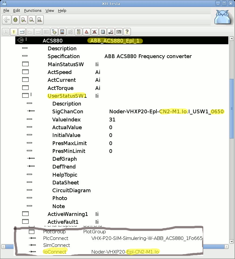
ABB Frequency Converter Settings
 To adapt the frequency converter to ABB_ACS880_Epl object some settings
 have to be performed. See examples Settings 1-4 below from a converter
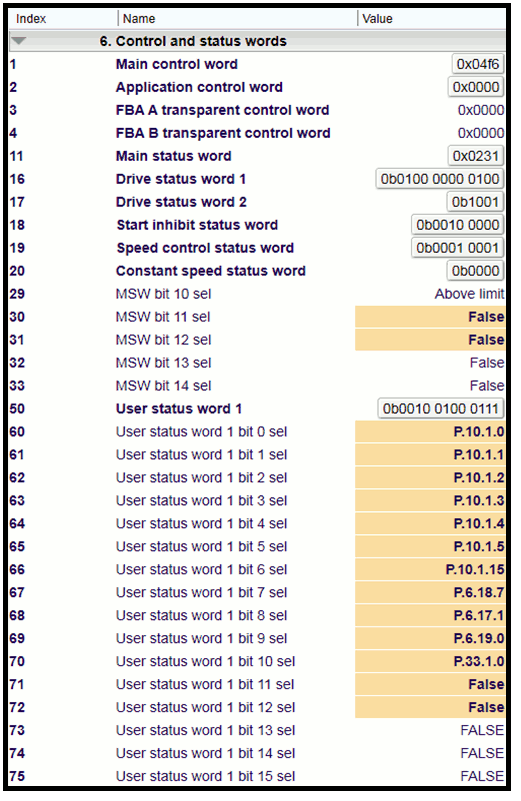
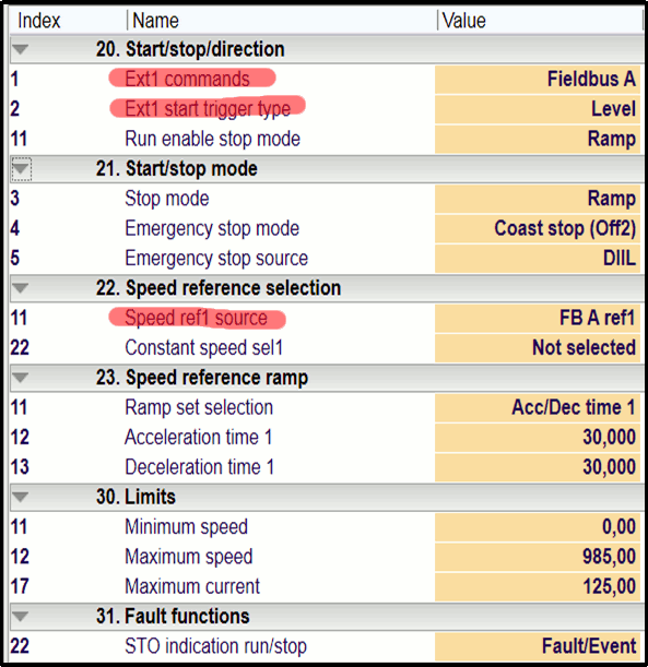
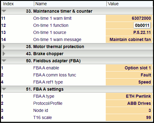
 controlling a pump. Values that differs from the default values are marked with
 orange color. Parameters marked with red color are set during startup, other
 orange value should be configured in the converter.

 The pictures are from the ABB Drive composer entry tool.

 The parameters are divided in parameter groups, for example 6.50 means group
 6 and index 50 (User status word). Some settings are pointing to the address of a
 value, for example group 6.66 is pointing to group 10.1.15 "DI status" bit 15
 which is DIIL digital input and 6.66 is reading by user status word 6.50 bit 6. User
 status word 6.50 is configured in 52.6 (PZD6) converter send area and will be
 read in channel I_USW1_0650 connected to signal UserStatusSW1 in class
 ABB_ACS880_Epl_1.

 FBA A means "Fieldbus Adapter Module slot A" in the converter. Note that
 the configuration requires that Profibus DP adapter module is placed in
 slot A, or the configuration has to be modified in the openCONFIGURATOR.
Settings 1
 Parameter group 6 index 60-75 specifies the bits in the User Status Word 1.
 The bits 11 to 15 (6.71 to 6.75) is free to use, the status of this bits
 are displayed in the object graph for class ABB_ACS880_1 named "User 1",
 "User 2" etc.

 Parameter group 6 index 30-33 specifies the bits in the Main Status Word
 (MSW), free to use.
Settings 2
 Parameter group 20 to 31 settings to be performed.
 NoteGroup 31 index 22 "STO indication run/stop" is important.
Settings 3
 Parameter group 33 to 50 settings to be performed.
 NoteGroup 50 index 2 "comm loss func" is important.
 Warning message 'change fan' in the driver need some settings in
 parameter group 33. 'On-time 1 Warn limit 33.11 is set to two
 years run time (63072000 seconds). 'On-time 1 source' 33.13 is
 pointing to bit status when fan is running i.e. P.5.22.11.
Settings 4
 Parameter group 52 data IN and 53 Data OUT in the converter specify
 the data exchange except reference word, CW word and SW word.

 Data out is data from ProviewR (PLC writing). Note that the parameters
 52.1 and 52.3 represents a 32 bit word and therefore allocates one more
 word in data in. The name of these words in class object
 ABB_ACS880_Epl_IoModule is I_CURR_0107 and I_TORQ_0110 respectively.

 Note that the reference word, control word CW and status word SW used by
 powerlink are missing here. Powerlink accesses these values directly.

Note Other setting of the converter are not discussed here.
Case study Powerlink tool openCONFIGURATOR
 openCONFIGURATOR is an open source tool contributed by www.kalycito.com.
 openCONFIGURATION is used for easy setup, configuration and maintenance
 of any POWERLINK network. openCONFIGURATOR ideally complements openPOWERLINK,
 the open source POWERLINK protocol stack for master and slave nodes.

 Every node in a Powerlink network must be configured in this openCONFIGURATOR
 tool. In a ProviewR project all Powerlink CN nodes memory mapping is a reflection
 of the memory mapping in a openCONFIGURATOR project.

 From the openCONFIGURATOR configuration a cdc file is generated. This file is
 used by the Powerlink stack to initialize the communication. The name of the
 cdc-file should be specified in hte Epl_MN object, attribute CDCfile. The default
 name is $pwrp_load/mnodb.cdc.

 A Powerlink network consists of two device types, MN (Managing Node)
 and one or several CN (Controlled Node).
Case study
 The case study example 11 to 20 below is an example that contains a project
 VHXP20 and one MN and one CN node. The CN node is an ABB frequency converter ACS880.
 Example 11 to 13 shows the ProviewR settings, the other examples is from the
 openCONFIGURATOR.

 Note It is recommended that you study the help in the openCONFIGURATOR
 before you study this case, see example 13 below how to start the openCONFIGURATOR.
Short description step by step:
  - Use the popup menu for an object of class Epl_MN to openCONFIGURATOR
  - Open existing project, in this case vhxp20.oct.
  - Make your changes and build the project. The will generate the cdc-file.
  - Transfer cdc file to $pwrp_load.
  - In ProviewR distribute function a copy command is needed for file mnobd.cdc
     to be copied to runtime environment location $pwrp_load.
  - Build the ProviewR project and distribute.
  - Note the bug in example 18.
Example 11 Settings in ProviewR Powerlink MN node
 Settings needed in ProviewR class Epl_MN node. Node id
 for MN node is always 240.

Example 11.1 Settings in ProviewR Directory
 Settings needed in ProviewR distribute function for binary file mnobd.cdc. This
 file is transfered via openCONFIGURATOR to $pwrp_load, see also example 20.
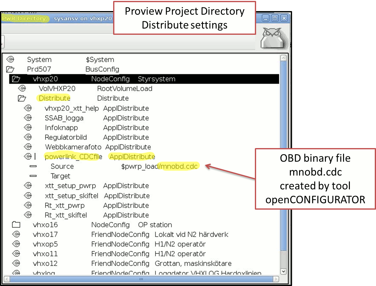
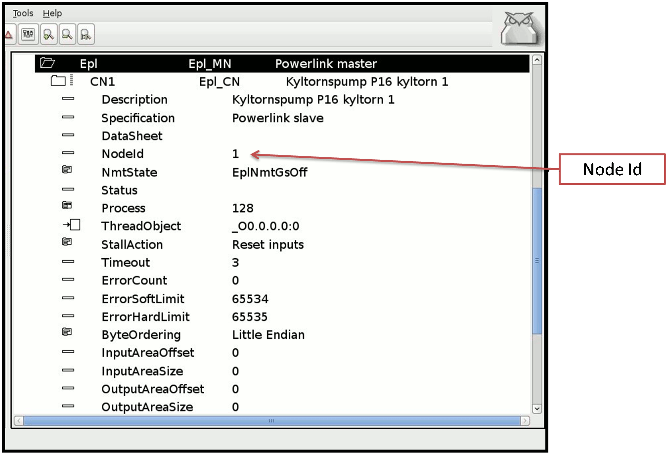
Example 12 Settings in ProviewR node CN
 Settings needed in ProviewR for class Epl_CN. The NodeId should
 be the same as in the openCONFIGURATOR.
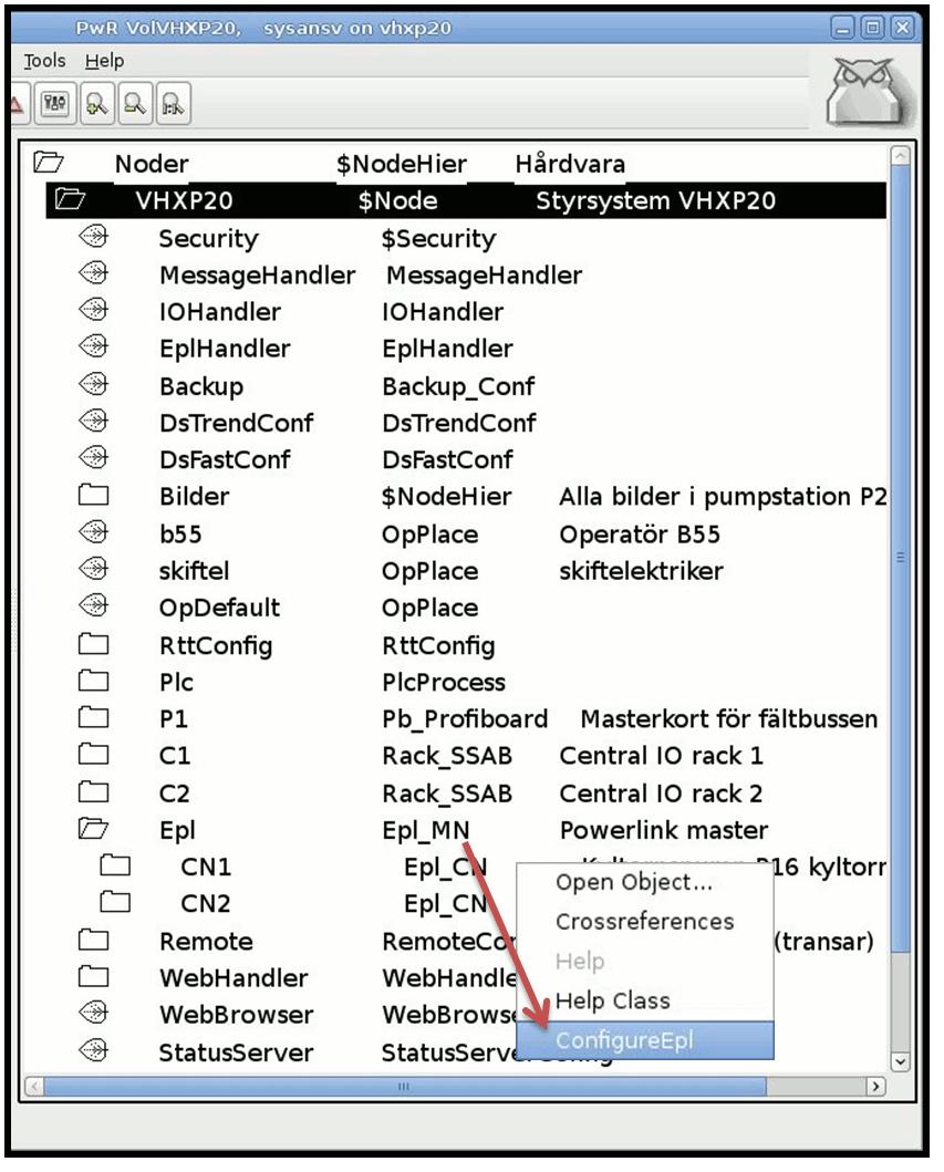
Example 13 Open the tool
Open the openCONFIGURATOR via objectclass Epl_MN node PopUp menu.
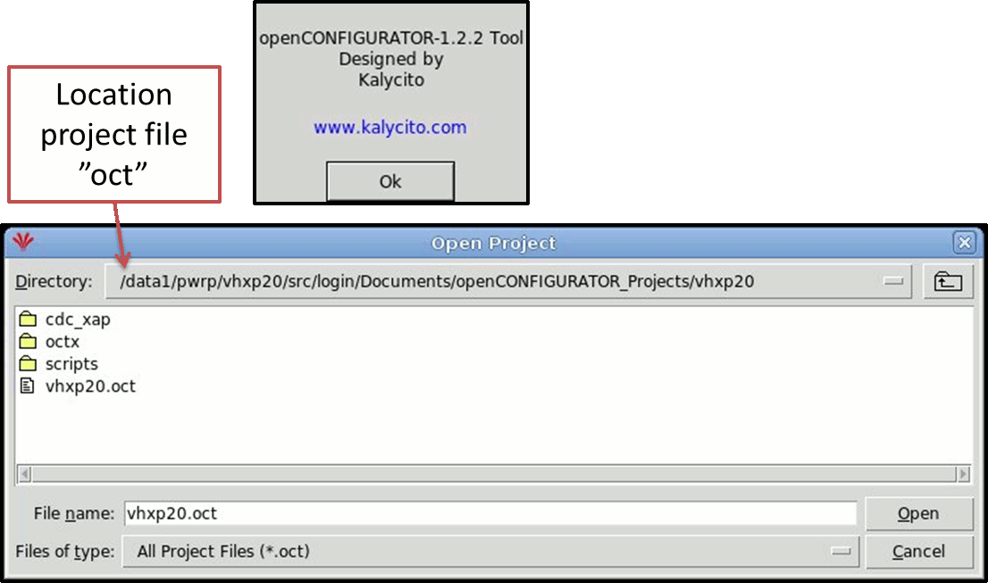
Example 14 Open project in the tool openCONFIGURATOR
 Select the project VHXP20 and open it. The folder
 $pwrp_login/Documents/openCONFIGURATOR_Projects/ is the standard path.
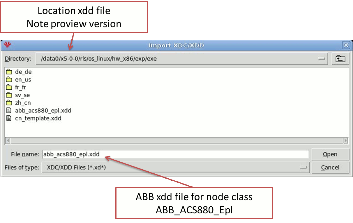
Example 14.1 Import the ABB ACS880 xdd file
 Create a new CN node and import the ABB xdd file from the $pwr_exe directory
 of the current ProviewR release. This file is prepared with all memory
 mapping (TPDO, RPDO) needed for the ProviewR class object ABB_ACS880_Epl.
 Build the project with project settings "auto generate" set to YES. Then follow
 example 18 to fix the ABB bug. After that you transfer the new mnobd.cdc
 file to ProviewR project $pwrp_load folder. Example 16 and 17 shows TPDO and
 RPDO memory mapping. Example 20 shows the script file "transfer.sh".
Example 15 Settings MN node and CN node
 This setting works fine in project VHXP20. You can see that the MN node id
 is 240 and the node id for CN node is 1 in this case. This id settings is
 the same in Prowiew project VHXP20.

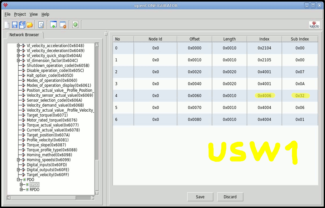
Example 16
 Memory mapping settings TPDO, reads data from the drive i.e SW, ACT, CURR,
 TORQ, USW1, WARN1, FAULT1 in this order.
 The yellow marked address is the user status word USW1, see example 16.1 that
 shows the corresponding ABB parameter (from ABB XDD file) i.e ABB group 6.50.
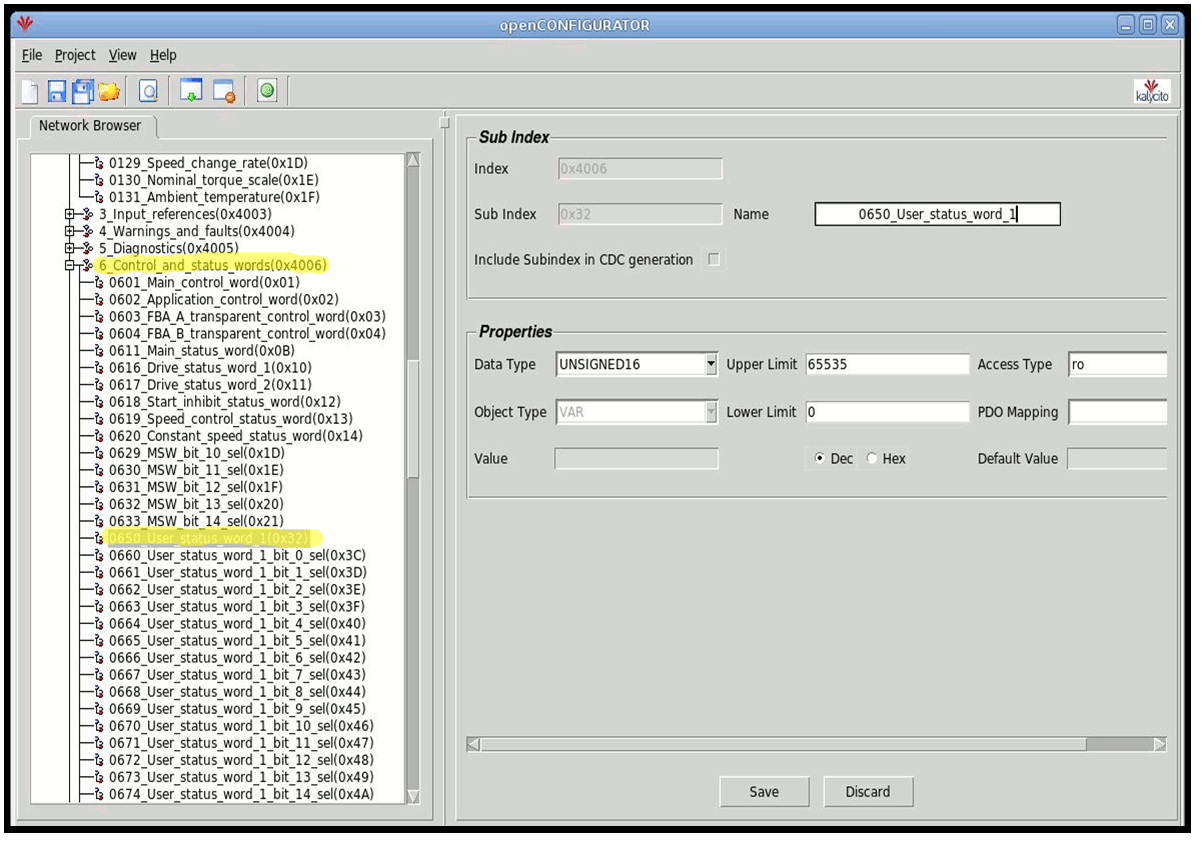
Example 16.1
 The yellow marked address 0x4006 index 0x32 is the address specification pointing
 to ABB parameter group 6.50 in the converter i.e user statusword 1 which is used
 by ProviewR to handle extra status as magnetized, zero speed etc.
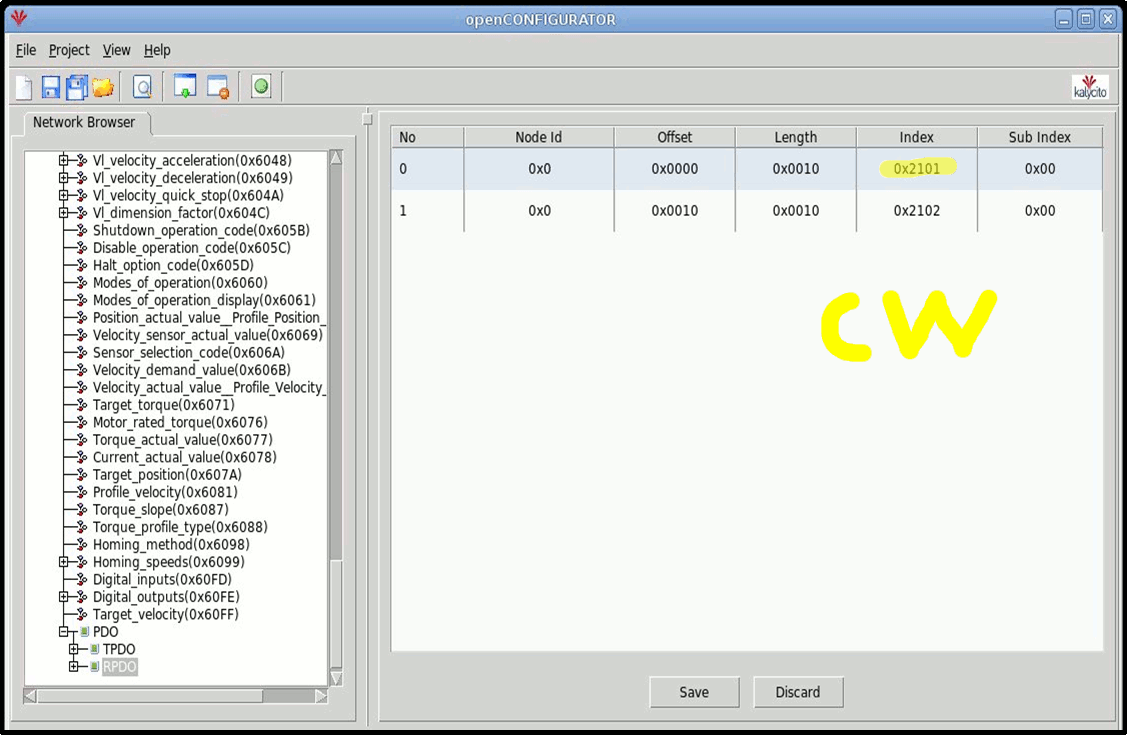
Example 17
 Memory mapping settings RPDO, writes data to the drive i.e controlword CW and REF
 word in this order. The yellow marked address is the control word CW, see example 17.1
 that shows the corresponding ABB parameter (from ABB XDD file).
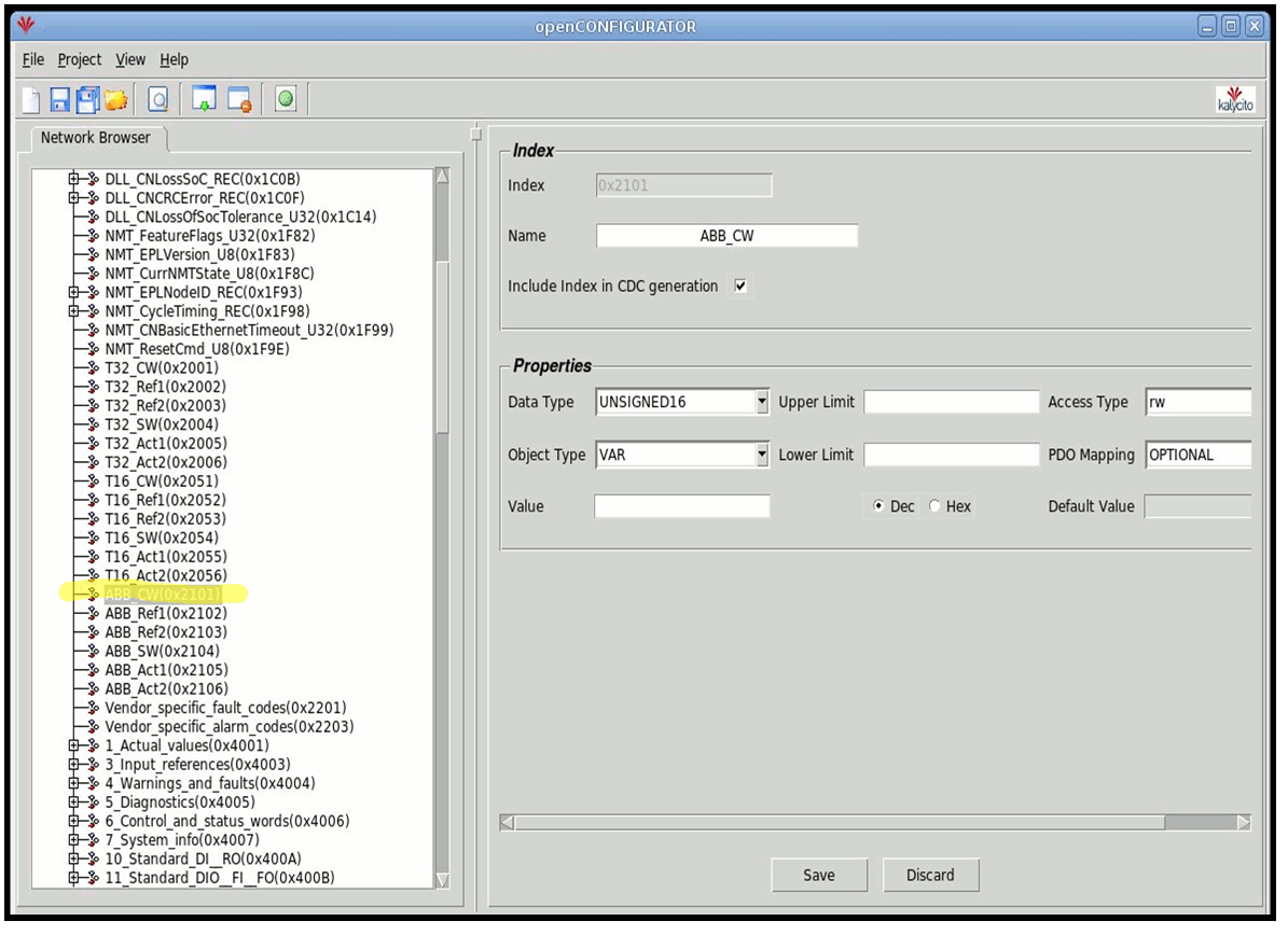
Example 17.1
 The yellow marked address 0x2101 is the address specification for Control Word in the converter which
 is used by ProviewR to start and stop the drive.
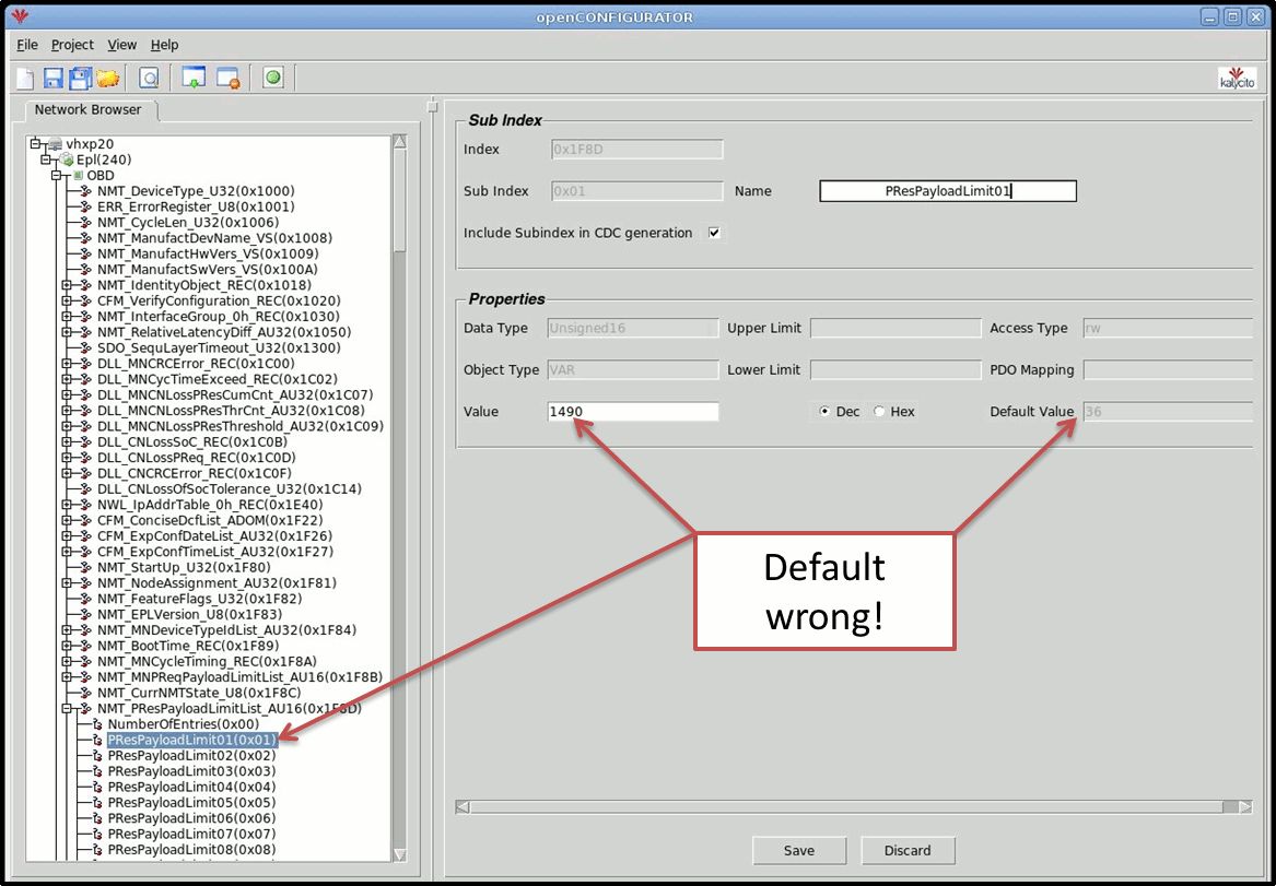
Example 18 (Bug in converter ACS880)
 Default value 36 is not correct in PResPayloadLimit01 under NMT_PResPayloadLimitList_AU16 in
 OBD data folder for node CN1. You must change the value to 1490 and build the project with project
 settings "auto generate" set to NO. Note the settings PResPayloadLimit02 is for node CN2 and
 PResPayloadLimit03 for node CN3 and so on.

 Every time you have built the project with auto generate YES, you have to do it again with auto
 generate set to NO. And you first have to change PResPayloadLimit01, 02, 03... value to 1490 for
 all ABB ASC880 nodes.
Example 19
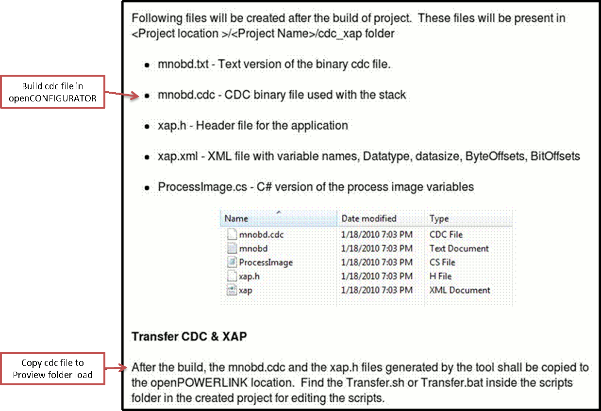
 Important files, good to know. You will also find auto generated txt/xml XDD files under
 ../..projects/octx folder for each node i.e 1.octx and 240.octx in this case
 (1 and 240 is NodeId).
Example 20
 This scrip tfile is executed by pressing Transfer in the openCONFIGURATOR toolbar,
 and in this case the CDC file will be copied to folder $pwrp_load as it should.

See also
| Template Object |
| Super.Specification |
ABB ACS880, ABB Drives communication profile |
| Super.DataSheet |
$pwr_lang/dsh/abb_acs880.html |
| Super.Process |
128 |
| Io.I_SW.Identity |
6.11 Main SW |
| Io.I_SW.ConversionOn |
1 |
| Io.I_SW.Representation |
3 |
| Io.I_ACT.Identity |
1.1 Act |
| Io.I_ACT.ConversionOn |
1 |
| Io.I_ACT.RawValRangeLow |
-2.000000e+04 |
| Io.I_ACT.RawValRangeHigh |
2.000000e+04 |
| Io.I_ACT.ChannelSigValRangeLow |
-2.000000e+04 |
| Io.I_ACT.ChannelSigValRangeHigh |
2.000000e+04 |
| Io.I_ACT.SensorPolyType |
1 |
| Io.I_ACT.SensorSigValRangeLow |
-2.000000e+04 |
| Io.I_ACT.SensorSigValRangeHigh |
2.000000e+04 |
| Io.I_ACT.ActValRangeLow |
-1.500000e+03 |
| Io.I_ACT.ActValRangeHigh |
1.500000e+03 |
| Io.I_ACT.Representation |
2 |
| Io.I_CURR_0107.Identity |
1.7 Current |
| Io.I_CURR_0107.ConversionOn |
1 |
| Io.I_CURR_0107.RawValRangeLow |
-3.000000e+06 |
| Io.I_CURR_0107.RawValRangeHigh |
3.000000e+06 |
| Io.I_CURR_0107.ChannelSigValRangeLow |
-3.000000e+06 |
| Io.I_CURR_0107.ChannelSigValRangeHigh |
3.000000e+06 |
| Io.I_CURR_0107.SensorPolyType |
1 |
| Io.I_CURR_0107.SensorSigValRangeLow |
-3.000000e+06 |
| Io.I_CURR_0107.SensorSigValRangeHigh |
3.000000e+06 |
| Io.I_CURR_0107.ActValRangeLow |
-3.000000e+04 |
| Io.I_CURR_0107.ActValRangeHigh |
3.000000e+04 |
| Io.I_TORQ_0110.Identity |
1.10 Torque |
| Io.I_TORQ_0110.ConversionOn |
1 |
| Io.I_TORQ_0110.RawValRangeLow |
-1.600000e+04 |
| Io.I_TORQ_0110.RawValRangeHigh |
1.600000e+04 |
| Io.I_TORQ_0110.ChannelSigValRangeLow |
-1.600000e+04 |
| Io.I_TORQ_0110.ChannelSigValRangeHigh |
1.600000e+04 |
| Io.I_TORQ_0110.SensorPolyType |
1 |
| Io.I_TORQ_0110.SensorSigValRangeLow |
-1.600000e+04 |
| Io.I_TORQ_0110.SensorSigValRangeHigh |
1.600000e+04 |
| Io.I_TORQ_0110.ActValRangeLow |
-1.600000e+03 |
| Io.I_TORQ_0110.ActValRangeHigh |
1.600000e+03 |
| Io.I_USW1_0650.Identity |
6.50 User SW1 |
| Io.I_USW1_0650.ConversionOn |
1 |
| Io.I_USW1_0650.Representation |
3 |
| Io.I_WARN1_0406.Identity |
4.6 Warn1 |
| Io.I_WARN1_0406.ConversionOn |
1 |
| Io.I_WARN1_0406.Representation |
3 |
| Io.I_FAULT1_0401.Identity |
4.1 Fault1 |
| Io.I_FAULT1_0401.ConversionOn |
1 |
| Io.I_FAULT1_0401.Representation |
3 |
| Io.O_CW.Identity |
6.1 Main CW |
| Io.O_CW.Representation |
3 |
| Io.O_REF.Identity |
3.5 Ref1 FB A |
| Io.O_REF.ActValRangeLow |
-1.500000e+03 |
| Io.O_REF.ActValRangeHigh |
1.500000e+03 |
| Io.O_REF.SensorSigValRangeLow |
-2.000000e+04 |
| Io.O_REF.SensorSigValRangeHigh |
2.000000e+04 |
| Io.O_REF.ChannelSigValRangeLow |
-2.000000e+04 |
| Io.O_REF.ChannelSigValRangeHigh |
2.000000e+04 |
| Io.O_REF.RawValRangeLow |
-2.000000e+04 |
| Io.O_REF.RawValRangeHigh |
2.000000e+04 |
| Io.O_REF.Representation |
2 |


