PLC program
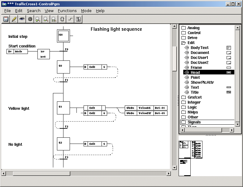
We use the Graphical PLC Editor to create PLC programs.
However first we must connect the PlcPgm object to a PlcThread object in the node hierarchy.
This states which timebase the PLC program is executed on.

Fig The Graphical PLC Editor
We will use the PLC Editor to create a sequential control program for the traffic lights. There
are two ways to solve the problem concerning the two operating modes for a traffic light,
normal and flash:
1. Use one Grafcet sequence with conditional branches, i.e. one branch for the normal operating
mode sequence and one for the flash operating mode sequence.
2. Use two separate Grafcet sequences with different start conditions.
Here we choose to use the second alternative. In chapter 4, Graphical PLC Programming a more
detailed description of Grafcet and sequential control can be found.
Grafcet programs are based on activating and deactivating a number of steps in sequence. In
linear sequences only one step at a time can be active. To each step you tie a number of orders
that are to be executed when the step is active. This can be e.g. to set (with a StoDo object)
a digital output signal, which turns on a lamp. The PLC programs thus control the logical
signals.

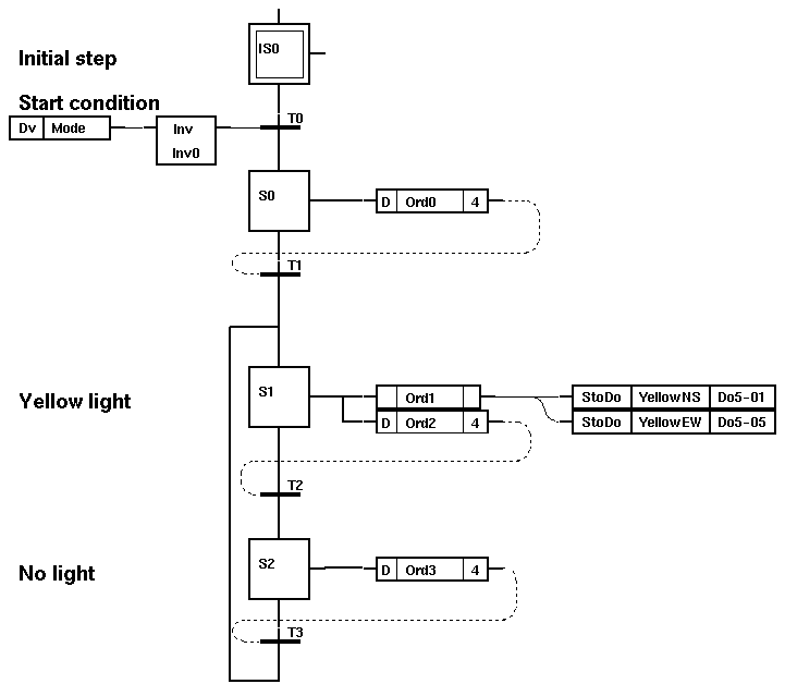
Fig The Flashing Light Sequence
This is the sequence that will be executed when you want the lights to flash yellow.
The start condition for this sequence is inverted in relation to the start condition for the
normal operating mode sequence. This implies that the two sequences cannot execute at the same
time.

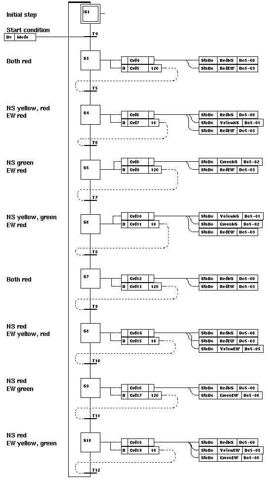
Fig The Normal Sequence
The program for the normal operating mode is based on a traffic light following the sequence:
| | North-South | West-East
|
| 1 | Red | Red
|
| 2 | Red, Yellow | Red
|
| 3 | Green | Red
|
| 4 | Yellow, Green | Red
|
| 5 | Red | Red
|
| 6 | Red | Red, Yellow
|
| 7 | Red | Green
|
| 8 | Red | Yellow, Green
|
| 9 | Back to step 1
|
|
|
The program starts in the initial step. If the start condition is fulfilled, step S1 will
become active and the red lamps are turned on. After a certain time, step S1 will become
inactive and step S2 will become active, and a yellow lamp will also be turned on, and so on.
When step S8 has been active for a certain time, it will be deactivated, and the initial step
is once again activated.

Fig Trigger Signals
The program above shows the logic that controls different operating modes.
At the very top to the right you set the Dv signal "Mode". If this is set to a logical 1, the
sequence for the light's normal operating mode will be run, otherwise the sequence for flashing
lights will be run.
The Dv signal "Reset" will be set to a logical 1 during one execution cycle when the signal
Mode changes value. This implies that the two Grafcet sequences will return to the initial
step. The chosen sequence will be executed again when Reset is set to a logical 0.
The PLC programs you have created must be compiled before they can be executed on a process
station.


