Plc Editor


In The Plc Editor you create plcprograms in a graphical programming language.

Programming with function block is made in a horizontal net of nodes and connections from left
to right in the document. Signals or attributes are fetched on the left side of the net, and
the values are transferred via connections from output pins to input pins of functions blocks.
The function blocks operate on the values, and on the left side of the net, the values are
stored in signals or attributes.

Grafcet sequences consist of a vertical net of nodes and connections. A state is transferred
between the steps in the sequence via the connections. Grafcet and function block nets can
interact with each other and be combined to one net.

Start

The Plc editor is opened from the configurator. Select an object of class PlcPgm and activate
'Functions/Open Program' (Ctrl/L) in the menu, or activate 'Open Program' in the popupmenu
for the PlcPgm object. The configurator should not be in edit mode.

Working mode

The Plc editor can be in four different modes: View, Edit, Trace and Simulate. The mode
is selected under 'Mode' in the menu.

View
In View you can look at the program, but not create or modify objects. The menu alternatives
for edit functions are dimmed.

Edit
If you have edit privileges you can enter the edit mode. Now it is possible to create and
modify objects.

Trace and Simulate
If you want to trace the program you enter the trace mode. This requires that the ProviewR
runtime environment is started in the development station. Simulate works as trace, but
you can also set values to signals.

Trace is easier and faster performed from Xtt. We recommend that you use PlcTrace in
Xtt instead.

Editing

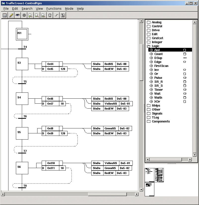
The Plc editor consist of

- a working area.
- tow palettes, one for function objects and one for connections (only one palette at a time
is visible).
- a navigation window, from which the working area can be scrolled and zoomed.

The Plc editor


The Palettes

The Object Palette
When you start the Plc editor, the function object palette is displayed. When creating a
function block in the work area, you choose a class in the palette.

The Connection Palette
When you create connections between objects, the editor chooses a suitable type of connection.
Though, in some cases the constructor has to influence the choice of connection type. This
is done in the connections palette that is displayed by activating 'View/Palette/Connection'
in the menu. When the palette is closed, by activating 'View/Palette/Object' or
'View/Palette/Plant', the editor is again responsible for choice of connection type.

Plant Hierarchy
You can view the plant hierarchy by activating 'View/Palette/Plant' in the menu. When
connecting function objects to signals, for example when fetching signal values, it is possible
to indicate which signal is to be fetched. You can also select the signal in the configurator,
which in many cases is a smoother alternative.

Navigation window

Down to the left there is a view of the program in reduced scale. The part of the working
area that is displayed in the main window, is marked with a rectangle. By moving the rectangle
(Drag MB1) you scroll the main window. You can also zoom with Drag MB2.

Function objects

Create object

To create objects the editor has to be in edit mode. Enter edit mode from 'Mode/Edit' in the
menu.

To create an object, you select a class in the palette, and click with MB2 (the middle button)
in the working area.

Modify an object

An object is created with certain default values. This applies also to which inputs and ouputs
are viewed in the plc editor and can be connected to other objects. If a value is to be changed
the object editor is opened for the object. The object editor is opened in following ways:

- doubleclick on the object
- activate 'Open Object' in the popup menu for the object.
- select the object and activate 'Functions/Open object' in the menu.


From the object editor you can change the values of various attributes. The attributes for a
plc object are separated into input attributes, internal attributes and output attributes.

Inputs
The value of an input attribute is fetched from another function block, via a connection.
The attribute is displayed in the function block as an input pin. In some cases the input is
not used, an and-gate has for example 8 inputs but often only two of them are used. This is
controlled by the 'Used' check box in the object editor. If 'Used' is marked, the attributes are
displayed with an input pin, else they are hidden.

Some input attributes, especially of analog type, can be assigned a value in the object editor.
If 'Used' isn't marked for the attribute, the assigned value is used. However, if 'Used' is
marked the value is fetched from the output the attribute is connected to. This is for
example the function for the limit values 'Min' and 'Max' in a Limit object. You can choose
whether to fetch the value from another function block, or to assign a value. The assignment
works in runtime as an initial value, that later can be modified in various ways.

Some digital inputs can be inverted. To do this you mark the check box 'Inverted' in the object
editor. In the function block this is displayed with a circle on the input pin.

Internal attributes
Internal attributes can contain configuration values that are assigned in the development
environment, or values that are calculated in runtime. The latter type is not changeable, and
maybe not even visible in the development environment.

Outputs
The value of an output attribute is transferred to an input via a connection. As for an input,
you can choose whether to display an output pin or not with the 'Used' check box in the
object editor.

Select an object

Objects are selected in the following ways

- click with MB1 on the object.
- Shift/Click MB1 adds the object to the list of selected objects, or removes it if the
object already is selected.
- by Drag MB1 you can select one or several objects. Objects that have some part within the
marked rectangle are selected.
- by pressing the Shift key and Drag MB1 you add the objects in the marked rectangle to the
selectlist.

Selected objects are drawn with red color.

Move objects

A single object is moved by placing the cursor on it and drag with MB1.
Several objects are moved by selecting them and dragging one of the objects with MB1.

Connections

Create connections

An output pin and an input pin is connected in the following way

- place the cursor on the pin, or in an area in the function object close to the pin, and
push MB2 (the middle button).
- drag the cursor to the other pin. or to an area in the function object close to the pin,
and release MB2.

A connection is now created between the objects.

Two inputs are connected in the same way, but some of the connected inputs have to be connected
to an output, and from this output the value is fetched to all the connected inputs.

Data types
The values that are transferred between different objects via the connections can be digital,
analog, integer or string values. Inputs and outputs that are connected have to be of the same
type. If they are of different type you have to use an object that converts between the types,
e.g AtoI or ItoA. These conversion objects are found under 'Signals/Conversion' in the palette.

Analog and integer connections are marked with slightly thicker lines, and digital connections
with thinner lines.

Furthermore there is a connectiontype for transfer of an object reference. These are drawn with
a thick, dashed line.

Reference connections
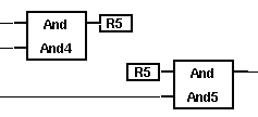
If the editor has difficulties to find a path for the connection between the input and output
pin, because there are too many objects in the way, or because they reside in different
documents, the connections are drawn as reference connections. Reference connections can also
be drawn by activating 'View/Reference connection' in the menu.

Reference connection


Execute order

Besides transferring a signal value, the connections also determine the execute order between
different function blocks. If two objects are connected trough an output and an input,
normally the output-object is to be executed before the input-object. But sometimes a feedback
is needed in the net, and then you face an execute order loop. To determine the execute order
you have to specify the feedback with a connection of type ConFeedbackDigital or
ConFeedbackAnalog. These are selected in the connection palette, viewed by activating
'View/Palette/Connection' in the menu. Under the folder 'ConPlc' you can find the feedback
connections. They are drawn with dashed lines.

Feedback connection


Here you can also find the connection type 'ConExecuteOrder'. In some cases you want to control
the execute order between to function blocks, though they are not connected to each other.
Then you can draw a ConExecuteOrder between them (between which input or output doesn't
matter). The connection is to be drawn from the object that is to execute first, to the object
that is to execute last. In the figure below, the storage of the attribute 'Temperaturer' is
done before the storage of the attribute 'Tjocklek'.

Execute order connection


Fetch and store signal values

Fetch signal and attribute values

In the left side of the net of function blocks, values of signals and attributes are fetched.
The fetching is performed by objects as GetDi, GetDo, GetDv, GetIi etc. Fetching of attribute
values is performed by GetDp, GetIp, GetAp and GetSp. These objects you find under the folder
'Signals' in the palette. When an object of this type is created, you have to state which
signal, or which attribute that is to be fetched. The easiest way to do this, is to select the
signal/attribute in the configurator, and click with Ctrl/Doubleclick MB1 on the object.
The signal/attribute is then displayed in the function block, and if the signal is an input
signal, the channel of the signal is also displayed.

There is a faster way to create these objects. If you draw a connection from an input pin in
a function object, and release it in an empty space in the working area, a generic Get object
is created with the datatype of the input, i.e. a GetDgeneric, a GetIgeneric, a GetAgeneric
or a GetSgeneric. When you specify the signal or attribute, the Get object is to fetch, the
generic Get object is converted to a Get object of the the correct type for the signal or
attrbute. If you choose a Dv in the configurator, a GetDgeneric will be converted to a GetDv
when clicking with Ctrl/Doubleclick MB1 on it.

Store signal and attribute values

In the right side of the net calculated values are stored in signals and attributes. The
storage is performed by objects as StoDo, StoDv, StoDp, StoIo etc. The method to specify the
signal or attribute to connect is the same as for Get objects, i.e. by selecting the
signal/attribute in the configurator and click with Ctrl/Doubleclick MB1 on the object.

If you draw a connection from an output pin in a function block, a generic Sto object is
created, that is converted to a Sto object of suitable type when connected to a signal or
attribute. If you want to store values with Set or Reset (for example SetDo or ResDo), you
can't use this method. You have to create the objects from the palette.

Generic Get and Sto objects


Subwindows

Some objects contain subwindow, e.g. CSub, SubStep, Trans, Order. An object with a subwindow
is marked with a thick gray line somewhere in the function block. A subwindow is opened in
different ways:
- by selecting the object and activate 'Function/Subwindow' in the menu.
- by activating 'Subwindow' in the popup menu for the object.
- by clicking on the object with Shift/Doubleclick MB1.

You create a new subwindow in the following way (the fact that only one editing session can
be open at a time, makes it a bit complicated)

- create the object that is going to contain the subwindow
- save
- open the subwindow
- leave edit mode in the main window
- enter edit mode in the subwindow

Control the execute order

You normally don't have to consider the execute order of different function blocks in a
window. As signals are I/O copied, i.e. every timebase in the plc program, makes a copy of
all signal values before the execution that is not changed throughout the execution. The
storing and fetching of signal values will not be affected by the execute order between
individual storing or fetching objects.

However, if you store and fetch the value of an attribute, that is not I/O copied, the
execute order can be of importance for the function.

The execute order is determined by the connections between the function blocks. The common
connections are both signal transferring and executeorder determining. If you make a feedback
you then have to choose a connectiontype that is signal transferring, but not executeorder
determining. The different feedback connections are of this type. Furthermore there is a
connection that is executeorder determining but node signal transferring, ConExecuteOrder.
With this you can control the execute order between different function blocks without
transferring any signals values.

The execute order for the function blocks in a plc window is displayed with
'View/Show execute order' in the menu. The number displayed for each function block states
the order in which they are executed. The object without a number doesn't have any
executable code.

The execute order between different PlcPgm is controlled by the attribute ExecuteOrder in the
PlcPgm object. Exectute order determines the order within a thread. Lower values of
ExecuteOrder are executed before higher.

Compile

Before a plc window can be executed, is has to be compiled. At the same time, a syntax control
of the plc code is performed. If the syntax in not correct, a message is displayed in the
message window. The error message can be of type Error or Warning. Error is a more severe error
that has to be attended to. By clicking on the arrow in front of the message in the message
window, the erroneous object is displayed in the plc editor.

After the syntax check, c-code is generated and sent to the c compiler. If there is an object
with user defined c-code, e.g CArithm or DataArithm, the c compiler can find errors that
are written in the terminal window. Always look in the terminal window to check that the
compilation succeeded.

The compile is executed from 'File/Build' in the menu.

If you want to check the syntax without generating any code, you activate 'File/Syntax'. The
c compiler is not activated, thus possible c code errors are not detected.

Cut and Paste

The plc editor contains a paste buffer. The paste buffer is common for all windows, which
makes it possible to copy between different windows. With the functions 'Edit/Copy' and
'Edit/Cut' in the menu, the selected objects are copied to the paste buffer (Cut also removes
them from the working area). The function 'Edit/Paste' copies the paste buffer to the working
area. The copied objects are now moved with the cursor, and you place them on the correct
position by clicking MB1 to lock them.

Cut, Copy and Paste can also be activated from the keyboard with Ctrl/X, Ctrl/C and Ctrl/V.

Special Plc objects

Here a number of objects that have special functions in the plc program are described.

Document
The document object is used to divide the code in pages, when printing the code. When you
open a new window, it contains a document object. From the object editor you can change the
dimension of the document, and enter signature and page number. Other information in the
document header is filled in automatically. The document object is found under the folder
'Edit' in the object palette.

ShowPlcAttr
ShowPlcAttr can be used as an extension of the document header. In the object is displayed
information about volume, scantime and reset object for Grafcet sequences.

Head, Title, Text and BodyText
These objects are used to write informational text in the document. Head, Title and Text
contains singleline texts of different size with max 79 characters. Bodytext contains a
multiline text with max 1023 characters. The objects are found under 'Edit' in the palette.

Point
The point object is a free connection point that is used to branch a connection or to control
the layout of a connection. Point is found under 'Edit' in the menu.

Grafcet
Grafcet sequences are built with specific Grafcet objects as InitStep, Step, Trans and Order.
The connections between the objects follow specific rules. The vertical pins in a Step object
are for example connected to Trans objects, and the horizontal pin is connected to an order
object. Here is an example of how to create a Grafcet sequence.

Start by creating an InitStop object. Draw a connection from the lower pin, and release it
in the working area below the InitStep object. Now a Trans object is created, that is
connected to the InitStep object. Draw a connection from the lower pin of the Trans object
and release it in the working space below the Trans object. A Step object is now created there.
If you draw a connection from the Step objects lower pin, another Trans object is created.
If you want a branch of the sequence, you draw an additional connection from the lower pin of
the Step object. Now a step divergence is created with specific StepDiv connections. If you in
the same manner create a branch from a Trans object, by drawing to two connections from the
lower pin, a parallel branch, with TransDiv connections marked with double lines is created.
If you draw a connection from the horizontal pin of a Step an Order object is created, and
so on. As you can see this is a fast way to build complex sequences.

ScanTime
ScanTime feches the actual scantime, i.e. the time since the last lap.

FirstScan
FirstScan is true the first lap of the plc execution after ProviewR startup. It is also true
after a soft restart.

Menu


File/Save                               Save
File/Print/Documents                       Print all documents
File/Print/Overview                       Print an overview
File/Print/Selected documents                       Print selected documents
File/Syntax                            Perform a syntax check of the code
File/Build                              Compile the program
File/Plc Attributes                       Open the Object editor for the PlcPgm object
File/Delete Window                       Delete the plc window
File/Save Trace                         Save trace objects
File/Restore Trace                      Restore previously saved traceobjects
File/Close                              Close the window
Edit/Undo Delete                        Undo the last delete action
Edit/Undo Select                        Reset the select list
Edit/Cut                                Cut selected objects
Edit/Copy                               Copy selected object to the paste buffer
Edit/Paste                              Copy the paste buffer to the work area
Edit/Connect                            Connect selected object to the selected signal or attribute
                           in the configurator
Edit/Delete                             Delete selected objects
Edit/Change Text                        Change text in the selected text object
Edit/Expand Object                       Expand the selected object
Edit/Compress Object                       Compress the selected object
Search/Object                           Search for an object name
Search/String                           Search for a string
Search/Next                             Search further with the same string
View/Palette/Object                       Display the functions object palette
View/Palette/Connection                       Display the connection palette
View/Palette/Plant                       Display the plant hierarchy
View/Reference connections                       Create connections as reference connections
View/Grid Size                          Set grid size
View/Show Grid                          Show the grid
View/Zoom/In                            Zoom in
View/Zoom/Out                           Zoom out
View/Zoom/Reset                         Reset to original zoom factor
View/Show Execute Order                       Show execute order for the functions objects
View/Redraw                             Redraw connections and redraw the window
Functions/Open Object                       Open the object editor for the selected object
Functions/Subwindow                       Open the subwindow for the selected object
Mode/View                               View mode
Mode/Edit                               Edit mode
Mode/Trace                              Trace mode
Mode/Simulate                           Simulate mode

Mouse functions

Working area

Click MB1                               Select an object. Click in an empty space will reset the select list
Shift/Click MB1                         Add object to the select list
DoubleClick MB1                         Open object editor
Shift+Ctrl/DoubleClick MB1                       Copy to past buffer. Click in an object
                        copies the object, click in empty space copies selected objects
Drag MB1                                On an object: move object or move selected objects
                               In empty space: select objects inside the marked rectangle
Shift/Drag MB1                          Add objects inside the marked rectangle to the select list
Click MB2                               Create object
DoubleClick MB2                         Delete. Click in object deletes the object, Click
                              in empty space deletes all the selected objects
Shift+Ctrl/Click MB2                       Paste. Copy the paste buffer to the working area
Shift+Ctrl/DoubleClick MB2                       Cut. Click in an object deletes the object, click
                              in an empty space deletes selected objects. Deletet object are put
                              in the paste buffer
Press MB3                               Popup menu

Navigation window

Drag MB1                                Scroll working area
Drag MB2                                Zoom working area